250kW On-Grid Energy Storage Solution Modular Container ESS for Commercial Buildings

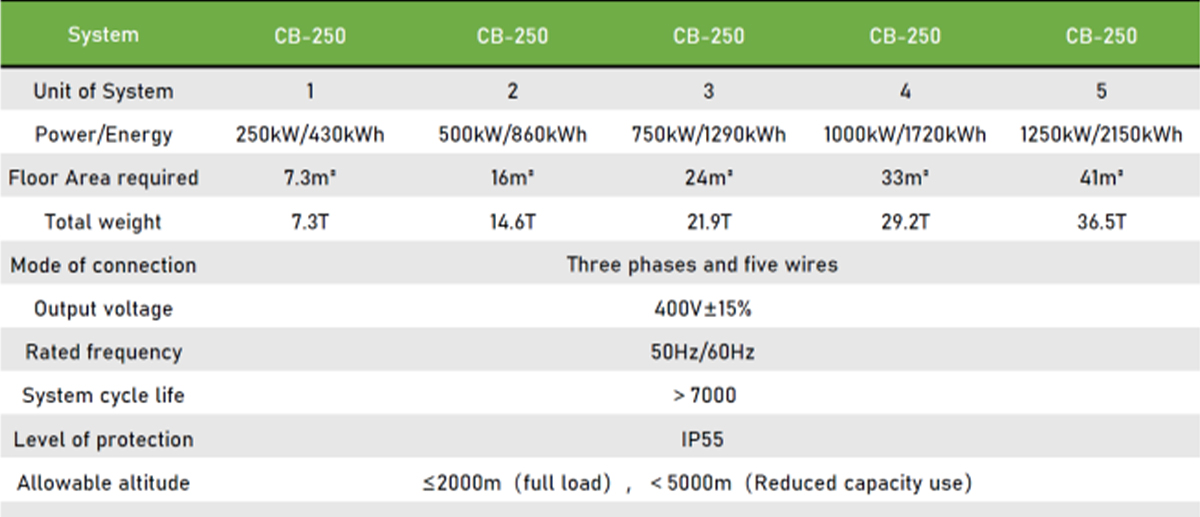
Product Range: 250kW/430kWh per module — scalable up to 1.25MW/2.15MWh (5 units in parallel) or fully customized.
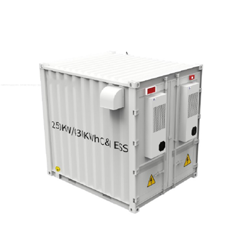
Design: Compact 10ft all-in-one air-cooled BESS for small to medium commercial and industrial applications.

This modular 10ft all-in-one commercial ESS is designed to make energy storage deployment simple, standardized, and scalable for businesses and industrial facilities. Equipped with top-tier LFP batteries and a high-performance grid-tied inverter, it delivers reliable performance across a wide range of commercial applications.

The integrated air-cooling system ensures safe and stable operation with a customized control system, even in demanding environments. As a standardized “energy package,” each container provides 250kW/430kWh, and up to five units can be paralleled, enabling capacity expansion from 100–1000kW / 200–2000kWh.

This containerized ESS supports peak shaving, backup power, electricity cost reduction, and power quality improvement. It can also be combined with PV systems or diesel generators to build a flexible microgrid for commercial and industrial users

local services, guaranteeing from concept to commissioning, to the most reliable operation and maintenance services

FEATURES

Power grid adaptability

Meet the smart grid design specifications and accept grid dispatch

Advanced islanding detection technology

Reactive power compensation technology

The isolated network operates independently

A full range of protection functions ensures safe and reliable

Over-voltage, under-voltage, over-current, high temperature, low temperature, communication abnormalities, system abnormalities, etc.

Comprehensive control strategies

Power smoothing, plan tracking

AGC frequency regulation

Peak and valley elimination & reduction

Maximum demand control

Emergency output

Comprehensive data

Comprehensive monitoring and management functions of energy storage power plant, covering detailed information of grid access, PCS and BMS system, to achieve data collection, processing, storage, query and analysis, visual monitoring, alarm management, statistical report, etc.

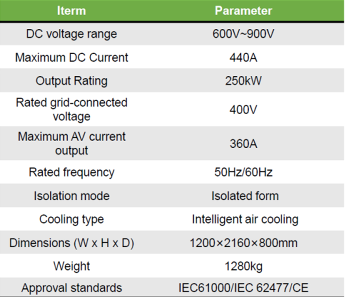
PRODUCT INFORMATION

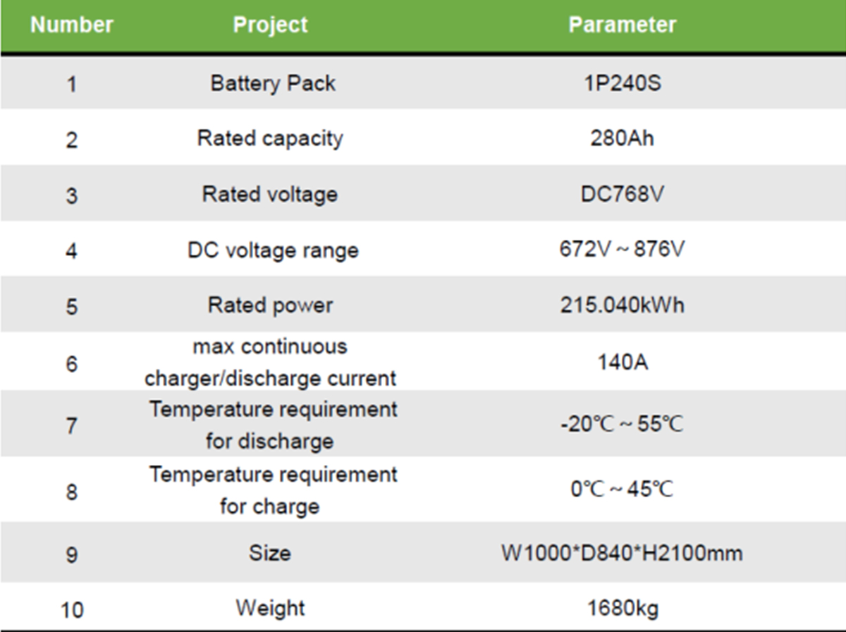
Battery Specification

battery pack 1P240Sparameters of the essPV + storage system BESS

How to Fully Understand Your Energy Storage Project Requirements?

Follow our 5 steps to build your energy stystem from concept to implementation

1. Provide Installation Site and Environmental Requirements

For example:

  • Altitude and potential derating issues
  • Coastal locations with salt-mist protection needs
  • High or low ambient temperature conditions

Understanding these factors in advance allows us to make the right design choices and prepare for necessary certifications.

2.Provide Clear Technical Specifications

List outs the loads, the electricity usages, working days and weekends, different seasns etc.
Loads curves and electricity bills etc.Understand the inrush current, maximum instantaneous power, and load startup requirements.

Such as:

  • Power and capacity (kW / kWh)
  • AC side voltage and frequency
  • Battery voltage range and battery type
  • Charge/discharge rate requirements

Clear technical requirements enable us to select the proper configuration and ensure seamless integration and production.

3.What type of energy system is connected to the grid? Or totally off-grid system?

  1. Is the system grid-connected, off-grid, or hybrid (on/off-grid)?
  2. If hybrid, will switching be manual or automatic?
  3. Are there other energy sources such as PV, wind turbines, or diesel generators?
  4. For PV systems, is the connection DC-coupled or AC-coupled?

Clarifying these points allows us to design the system topology accurately.

4.What Is The Operating Modes of the Energy Storage System

Based on the topology, we will discuss the expected functions and operating logic, such as:

  • Self consumption
  • Peak shaving and valley filling
  • Demand management
  • Participation in energy trading
  • Integration with third-party EMS platforms
  • Logic of on/off-grid switching

Once these are defined, we can estimate the system’s potential economic benefits.

5.Finalize project Supply Scope, Performance Targets, and Delivery Details

The supply scope and performance specifications

Delivery schedule and location

Electrical design, site layout, and construction drawings

Collect information again for installation

With these steps, your energy storage project moves smoothly from concept to implementation.

If anything is unclear, we will provide you a form to fill out to collect all necessary information, or shcedule a call for clarification.

Highlight:Once you choose us as your supplier, our engineers will visit your site to confirm requirements, design the solution, and guide the full installation process.

Projet and Solution Cases

The system capacity can be flexibly configured and expendable or update in the future.

Once Project Proposal ---for Hybrid Energy Storage System

1. Known Data

Item Description Value
Peak Load Power Maximum simultaneous load 234 kW
Daily Energy Consumption 234 kW × 12 h 2,808 kWh/day
System Losses Considered 20% total (PV, inverter, cable, etc.)
Required PV Generation 2,808 ÷ 0.8 3,510 kWh/day

2. PV System Sizing (Based on 6.5 Peak Sun Hours)

Required daily generation (after system losses): 3,510 kWh/day

Effective Sun Hours (PSH): 6.5 h/day

Calculated PV Installed Capacity (DC):
3,510 ÷ 6.5 = ≈540 kW (DC)

Recommendation:
To ensure stable generation under cloudy conditions and allow for degradation, it is advised to install 550–600 kW (DC).

DC/AC Ratio: 1.5
Required Inverter Capacity (AC): 540 ÷ 1.5 = 360 kW (AC)

3. Inverter Configuration

Theoretical Capacity: 360 kW (AC)

Recommended :Total capacity 360–400 kW (AC)

Suggested combinations:
• 2 × 200 kW units, or
• 3 × 125–150 kW units

4.Battery Capacity Calculation


Design Requirement: 4-hour discharge at full load (234 kW × 4 h = 936 kWh)

Assumptions:

ParameterValue
Battery round-trip efficiency90%
PCS / Inverter efficiency95%
Depth of Discharge (DoD)80%

Effective Factor: 0.90 × 0.95 × 0.80 = 0.684

Nominal Battery Capacity: 936 ÷ 0.684 = ≈ 1,368 kWh (≈ 1.37 MWh)

Recommendation: To compensate for capacity fade and ensure long‑term reliability, install 1.4 – 1.5 MWh (nominal capacity).
It is advisable to specify in the contract that acceptance is based on usable capacity after degradation.


5. Discharge Rate (C-rate) Verification

Parameter

Value

Continuous Discharge Power

234 kW

Nominal Capacity

1,368 kWh

Calculated C-rate

234 ÷ 1,368 = 0.17 C (≈1/6C)

Conclusion:
The discharge rate is low, which ensures high system reliability, low thermal stress, and extended battery lifetime.

More cases

Commercial Battery solution provider

Off-grid system: PV, ESS and Diesel Generator

Commercial Battery solution provider

Hybrid System/on-off grd system: PV, ESS,Diesel Generator And Mcro-grid control system

Warranty/Compliance/ Service

Warranty: standard 5 years, extendable to 10 years.

Compliance: certificated and compliant with your region regulation.

Services: fast response, fast delivery, training for installation and on-site support available.

To better serve you, we are gradually establishing local teams and warehouses overseas.

Our highly competitive products can help you stand out in a competitive market.

Ask any question for your C & I project?

Contact Us Immediately